400 kV Substation
- Client
- Hartek Power Pvt. Ltd.
- Scope
- Earthing design and calculation using CDEGS

Infrastructure sector
Electrical, civil and structural design for air-insulated and gas-insulated substations and switchyards, AC up to 765 kV: new stations, bay extensions, interconnecting transformer yards and line bays.
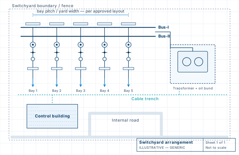
Awarded substation packages that need the electrical or civil design, or both, developed to the utility’s specification and taken through approval.
Pooling, evacuation and dedicated grid-connection substations where the station is part of a larger plant.
Teams that need vendor documents, calculations or drawings checked against the specification.
An illustrative 765/400/220 kV arrangement is shown on the home page.
| Type | What drives the design | Typical engineering focus |
|---|---|---|
| AIS (air-insulated) | Phase and ground clearances, bus arrangement and yard area | Yard GA and sections, flexible or rigid bus, SCF and sag-tension, gantries, DSLP, earthing |
| GIS (gas-insulated) | The supplier’s equipment layout and the building that houses it | Hall layout and interfaces, cable and bus-duct entries, building, crane and floor loads, earthing of enclosures |
| Extensions and hybrid | Existing station data and the interface with operating equipment | Interface drawings, matching of bus levels and earthing, outage-aware sequencing of drawings |
| Bus schemes | Reliability and switching needs set by the utility | Breaker-and-a-half at 765 kV and 400 kV, double main and transfer at 220 kV, and other schemes as specified |
The contract and MDL decide what a given package contains.
| Input | Typically from | Used for |
|---|---|---|
| Single-line diagram, bay list, utility criteria | Client or utility | Bus scheme, ratings and arrangement |
| Fault level and system data | Client or system study | Equipment ratings, earthing, conductor and SCF design |
| Equipment GTP and vendor drawings | Suppliers | Dimensions, weights, terminal loads, clearances |
| Survey and geotechnical report | Client or surveyor | Grading, foundations, earthing soil model |
| Specification and MDL | Client | Deliverables, formats, codes and revision convention |
| Interface | What is coordinated |
|---|---|
| Transformer and reactor yard | Plinth, oil pit, firewall, bushing clearances, NGR and neutral connections |
| Line entries | Gantry position, tension and swing, line-side equipment, shield wire termination |
| GIS building | Equipment loads, openings, crane, cable and bus-duct entries, earthing |
| Control building | Panel layout, cable entries, auxiliary supplies, lighting and earthing |
| Equipment suppliers | GTP, outline drawings, terminal loads and mounting details |
Client is the company that awarded CoreGrid the work. Owners and locations are not shown.
Send us the tender extract, single-line diagram, master deliverable list or the specific calculation you need. We will confirm scope, inputs and a realistic submission sequence before any work starts.