33/220 kV Pooling Substation
- Client
- Anandshree Renewables
- Scope
- Complete detailed engineering consultancy

Infrastructure sector
Plant electrical balance of system, collection networks, layout interfaces and grid connection for utility-scale solar, wind and hybrid projects. Pooling substations and battery storage have their own pages.
We usually work for the EPC contractor. Owner and site names are not published on this website.
| Party | Typical role on a renewable project |
|---|---|
| Plant owner or developer | Owns the plant, obtains connection approval and sets the project requirements |
| EPC contractor | Designs, procures and builds the plant, pooling substation and evacuation works under contract |
| Utility or transmission licensee | Owns the receiving substation and grid; sets metering, protection and SCADA requirements |
| Equipment OEMs | Design their own modules, inverters, turbines and battery systems and supply their data |
| CoreGrid Engineering | Prepares the engineering the client contracts for: electrical and civil design, studies by scope and document review |
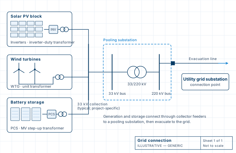
A solar plant is a set of PV blocks, each with inverters and an inverter-duty transformer, connected by collector feeders to the plant or pooling substation. Its electrical design decides losses, protection and how the plant meets the grid’s connection requirements.
Within a contracted scope we prepare the plant’s electrical balance of system: inverter and transformer sizing interfaces with the suppliers, DC and AC collection cable sizing and layout, LT and HT single-line diagrams, earthing and lightning protection, auxiliary supplies, and the power evacuation scheme. We coordinate the plant layout with civil design for foundations, trenches and access.
A wind farm connects each turbine generator (WTG) through its unit transformer to medium-voltage collector circuits, commonly at 33 kV, which run to the pooling substation. Turbine spacing and terrain make the collection network long, so cable or overhead collector sizing, losses and protection grouping matter.
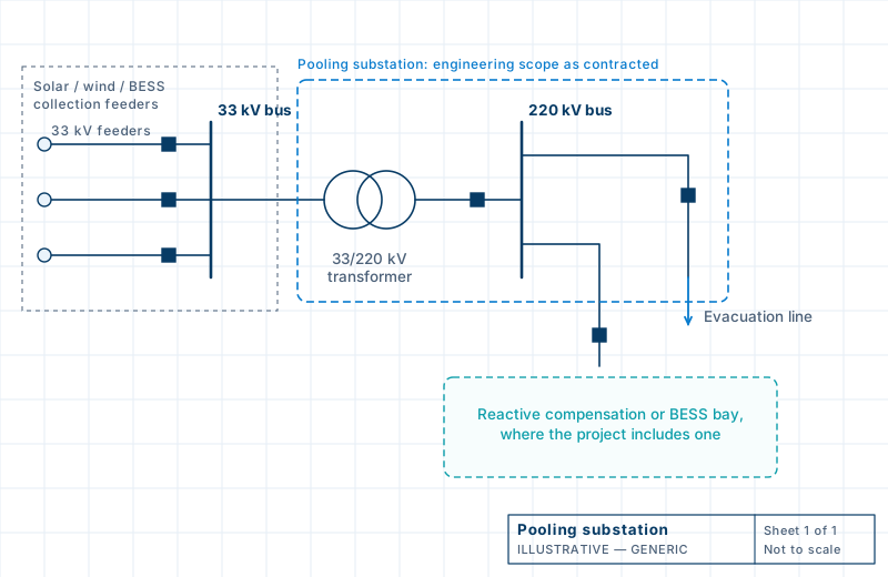
Within a contracted scope we design the collector system and feeder grouping, MV cable or line routing, turbine transformer and feeder interfaces, the pooling substation and switchyard electrical and civil design, earthing, metering, and the SCADA and utility interfaces for evacuation. Turbine design is the OEM’s responsibility.
Hybrid plants combine solar and wind, sometimes with storage, behind one connection point. The engineering challenge is the shared infrastructure: collector circuits and pooling bays that serve both sources, an evacuation transformer and bay sized for the combined output, protection and control that coordinate the sources, and metering and reactive-power arrangements that meet the connection requirement.
Generation and storage connect through collector feeders to a pooling substation, which steps the voltage up to 132 kV, 220 kV or higher. An evacuation line then carries the power to the utility’s receiving substation, where metering, protection and SCADA requirements apply.
System studies such as load flow, short circuit, reactive power capability and harmonic analysis support the connection where the project commissions them. Each is offered on a stated basis; see engineering studies.
How each renewable activity is offered. We confirm the exact scope in writing for every project.
| Activity | Basis |
|---|---|
| Plant electrical balance of system, collection networks, SLDs, earthing | Offered as detailed engineering |
| Pooling and evacuation substation electrical and civil design | Offered as detailed engineering |
| Plant layout and equipment selection interfaces with suppliers | Offered, coordinated with OEM data |
| Feasibility, load flow and grid integration studies | By scope, confirmed at enquiry |
| Resource assessment and energy-yield estimates | By scope, confirmed at enquiry |
| Performance testing and commissioning support | As contracted; see site support |
| Module, inverter, turbine and battery equipment design | OEM responsibility |
Send us the tender extract, single-line diagram, master deliverable list or the specific calculation you need. We will confirm scope, inputs and a realistic submission sequence before any work starts.